

WELDING SYMBOLS
UNDERSTANDING STANDARD AWS WELDING SYMBOLS
INTRODUCTION
A welding symbol is made from a standardized library of symbols and elements, which when assembled together, convey specific welding information.
The minimum elements required to create a welding symbol are the reference line, arrow and the weld symbol. Supplementary elements can also be included on the welding symbol, things such as the field weld flag, all-around symbol, weld contour symbols, and dimensions for groove and fillet welds.
AWS A2.4 Standard Symbols for Welding, Brazing, and Nondestructive Examination is the governing code regarding welding symbols, and it makes the following distinction.
Weld Symbol: The symbol representing the type of weld; it is placed on the reference line, and when used, is part of the Welding Symbol (see Welding Symbol)
Welding Symbol: The assembly of the elements of the reference line, arrow and weld symbol, constitute the required elements of a welding symbol. Additional elements from the welding symbol library may be included to convey additional specific welding information.
The welding symbol is the most effective, compact, and standardized way to communicate required welding information specific to each weld. More generalized welding information is communicated by drawing notes, drawing details, specifications, codes, and welding procedures.
Welding symbols have a standardized but often poorly understood system; this is mostly due to the lack of properly structured training, reference materials, and access to the welding symbol standard itself. The following article covers the basics that anyone working with welding symbols will find useful.
BASIC ELEMENTS OF A WELDING SYMBOL
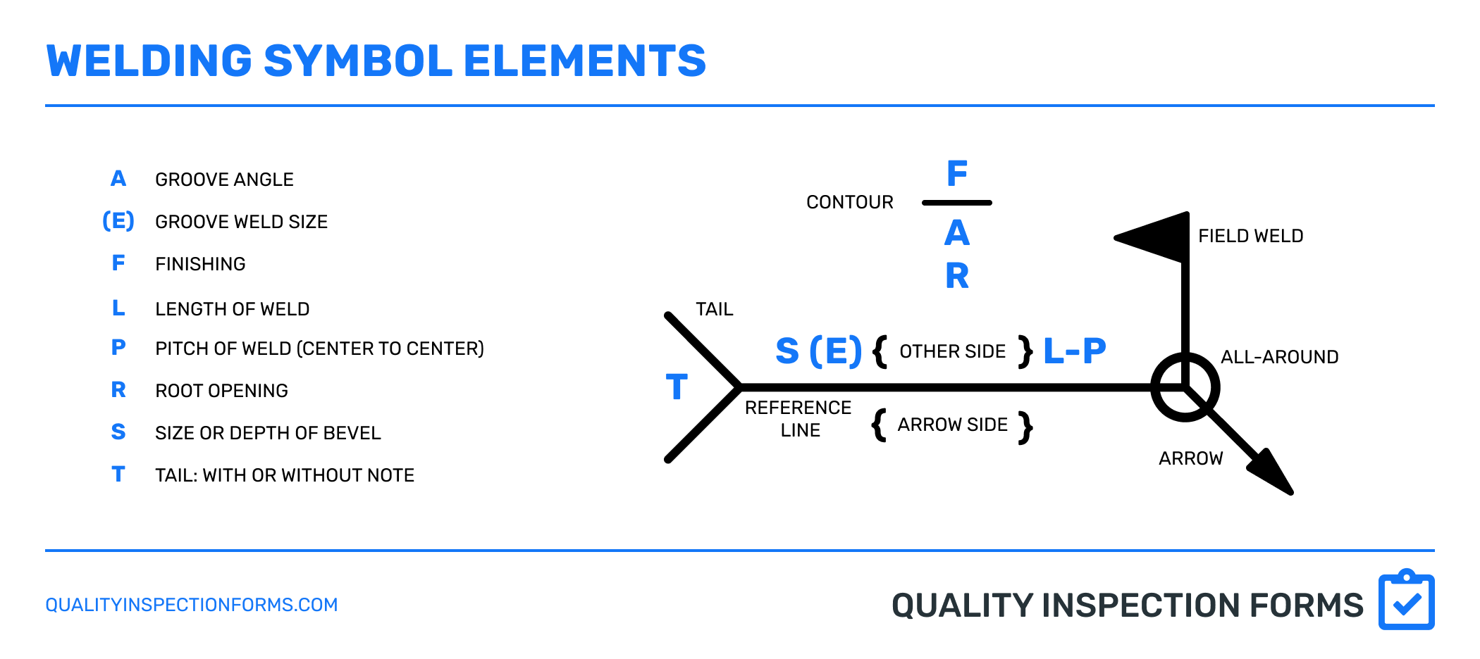
Elements of an AWS Welding Symbol
BASIC WELD SYMBOLS
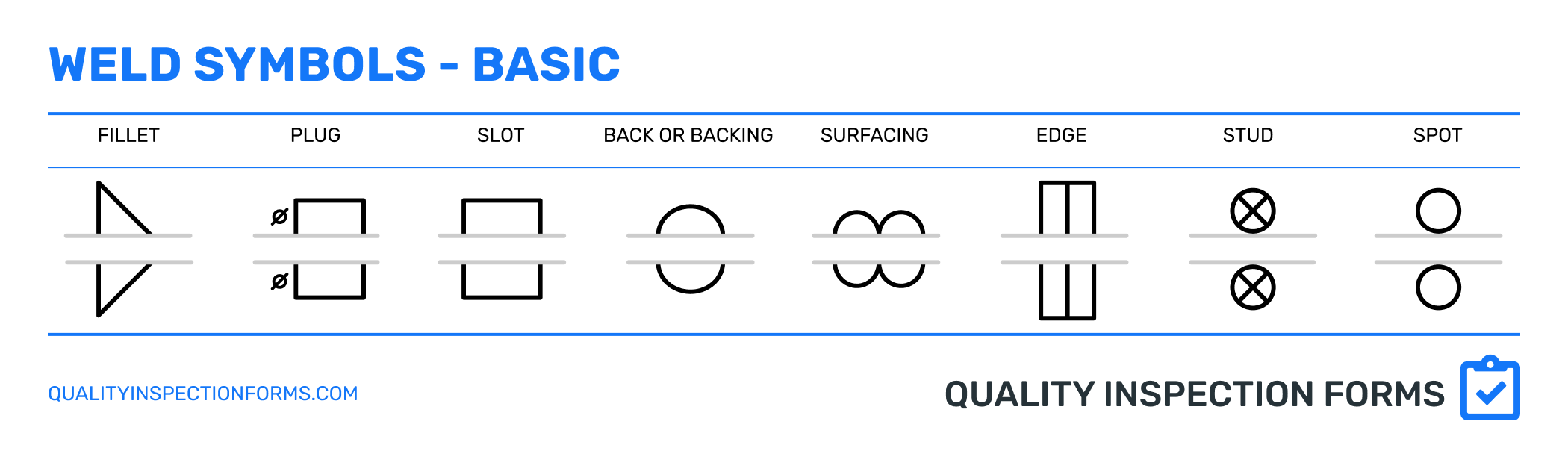
Basic AWS Weld Symbols
SUPPLEMENTARY WELD SYMBOLS

Supplementary Weld Symbols
GROOVE WELD SYMBOLS
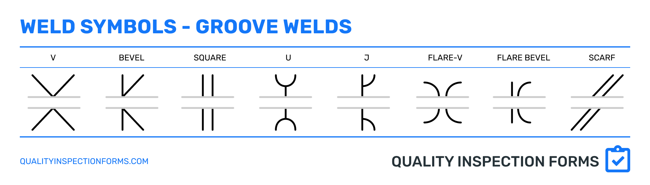
Groove AWS Weld Symbols
BASIC TYPES OF JOINTS

AWS Basic Weld Joint Types
ARROW SIDE & OTHER SIDE
There is significance of where the weld symbol is placed in relationship with being above or below the reference line of the welding symbol.
The top and bottom of the reference line have been broken into two distinct groups, the Arrow Side and Other Side.
Arrow Side: Information placed on the bottom of the Reference Line is associated with the side of the joint facing the arrow.
Other Side: Information placed on the top of the Reference Line is associated with the side of the joint on the other side or opposite side from the arrow
The top or bottom of the arrow is determined the same as up or down for the rest of the items on the drawing and is anchored in reference to the title block of the drawing.

AWS Welding Symbols for Arrow and Other Side
The arrow side and other side of a joint are determined by their respective side position along the joint’s plane in respect to the placement of the welding symbol arrow.

AWS Welding Symbols for Arrow and Other Side
FILLET WELDS
Fillet weld dimensions primarily consist of Size, Length & Pitch, as depicted in the diagram below. If “L” or “P” are not defined, the weld is meant to be continuous for the joint’s length.

AWS Welding Symbol for Fillet Welds
Fillet weld applications include continuous or intermittent conditions. Continuous welds will run the full length of the joint, where intermittent welds will only cover a portion. A Stitch Weld is a common nonstandard term for intermittent welds.
Intermittent fillet welds can be specified as a chain or staggered.
Chain layouts place the fillet welds exactly opposite each other through the length of the joint.
Staggered layouts place the opposing fillet welds in a staggered position, where fillet welds are approximately centered between the gap on the joint’s opposite side.

AWS Fillet Welding Examples for Chain vs Staggered
The pitch of intermittent fillet welds is the distance between the centers of successive and adjacent weld segments down one side of the joint. For example, a 4” pitch places the center of adjacent fillet welds at 4” center to center.
As an example a 2-4 intermittent fillet weld, will create a 2” long weld on 4” centers. The layout of this callout will leave 2” between the end of one weld and the start of the next as shown in the following reference.

Welding Symbol Layout of Pitch for Fillet Welds
Care should be taken to prevent the incorrect practice of the pitch being the distance between the end of a weld and the start of the next. This creates a condition where an insufficient amount of weld is placed in the joint and does not conform to the specified layout or necessary strength requirements.

AWS Welding Symbol - Layout of Fillet Welds
The fillet weld size specifies the length of the legs of the fillet weld. A fillet weld inspection gauge is used to measure the leg length.

How to use Fillet Welding Gauges
The size of a fillet weld is specified on the left side of the fillet weld symbol.

AWS Welding Symbol with Arrow vs Other Side
CJP & PJP
A CJP or a Complete Joint Penetration weld is a weld in which weld metal extends through the full thickness of the base material being welded.
A PJP or Partial Joint Penetration weld is a weld in which the weld metal extends through a portion of the base material being welded.

CJP Complete Joint Penetration and PJP Partial Joint Penetration Joints
EXAMPLES OF WELD SYMBOL DIMENSIONS
Omitting the depth of bevel and groove weld size dimensions from the welding symbol requires complete joint penetration.
The following table demonstrates how the weld symbol dimensions are applied across the standard groove symbols.

AWS Welding Symbol for Groove Weld Elements