

WHAT IS WELD MAPPING?
HOW WELD MAPS & WELD LOGS WORK TOGETHER
WELD MAP
A weld map is a version of the drawing used to number each of the welds or joints contained within it. The process of numbering or annotating each weld’s location is what turns a standard drawing into a weld map. See the weld map example below; this example includes nine welds and two segments or piping spools. You can find these nine welds documented on the weld log example later in the article.
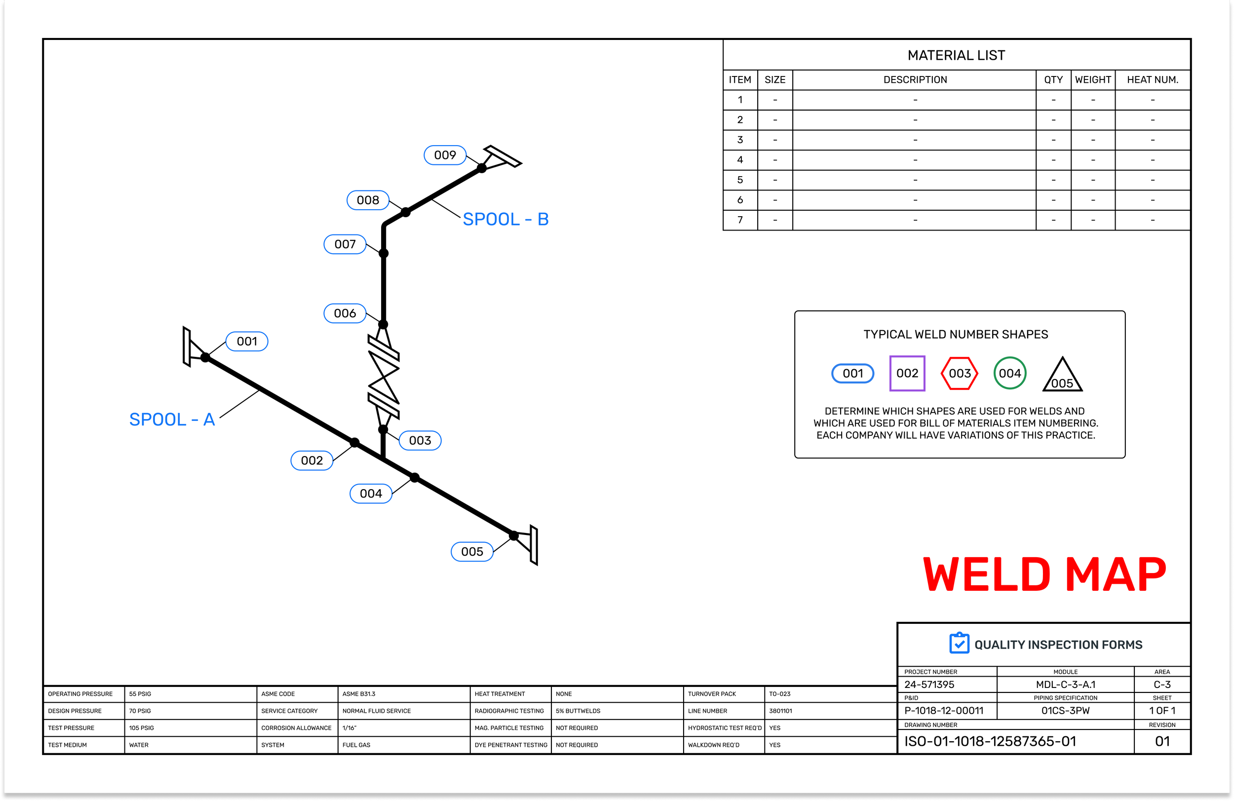
Typical Weld Map Example above, the numbered welds on this map correspond with the rows of the Weld Log below
WELD LOG
A weld log is a table style document that contains data in rows and columns used to document weld details.
Weld log rows correspond to the numbered joints on the weld map. Weld log columns correspond to the required documentation or inspection points for the weld.
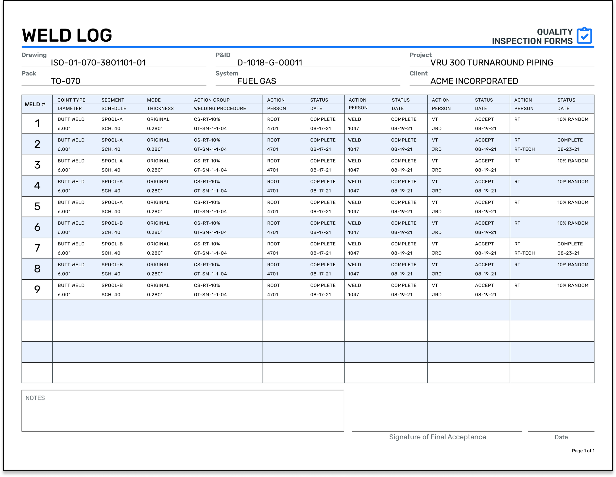
Typical Weld Log Example, the numbered welds on this form correspond with the numbered annotations on the Weld Map above
HOW DO YOU USE A WELD MAP and WELD LOG TOGETHER?
The weld map is the foundational document for creating a weld log. The numbered joints on a weld map correspond to the numbered rows of the weld log. Both the Weld Map and Weld Log are then used in tandem. The benefit of the weld map is that it creates the weld’s visual position on the drawing. The advantage of the weld log is that it documents the who, what, when, and how of the weld.
In some limited cases, all the weld details are included on the weld map, and no separate log is generated; In these situations, the project requirements must allow for this approach. In these cases, there may be a small table applied directly to the weld map, often in the area of the bill of materials. Embedding the log on the map can create a confusing situation for what to call the document, but this is still referred to as the weld map. This situation primarily exists in pipe spool fab shops and structural shops. The disadvantage of the combined map & log is that the ability to effectively track the progress of welds and maintain the cleanliness of documentation used to turnover to the client. In most cases, many data fields must be documented, more than can be squeezed into the space available on a drawing, and this creates the “weld map + weld log” approach.
WHAT SHAPE SHOULD I USE FOR WELD MAPPING?
The styles of annotations used for the weld numbering can vary between companies. Most situations involving manual mapping utilize common shapes found on drawing stencils, the hexagon, circle, or square being the most common. The weld number annotation style must also consider what shapes have already been utilized by the drawing to communicate item numbers and other such things. It is advisable to follow a company standard that helps the project team distinguish between weld numbers and item numbers. Welding codes do not specify the shape of the annotation used in weld mapping. In some cases, a company's past practices, quality manuals, or client specifications may designate what is used.
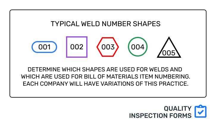
Typical Weld Numbering Shapes
WHAT IS TYPICALLY INCLUDED ON A WELD LOG FORM?
Weld log / Weld Summary Report columns typically include
Weld number
Joint type
Size or diameter
Thickness
Welding procedure
Fit
Fit checks
Stamps of welders involved
Weld dates
Initials of inspectors involved
Inspection dates
Material traceability of the parts joined as well as the filler metal
In piping applications what segment or spool number the joint is associated with
WHEN ARE WELD MAPS & LOGS REQUIRED?
Weld maps & weld logs are standard where required by contract, project specifications, quality program requirements, and where there is an elevated level of risk; as risk increases, so do the inspections and documentation level. Each welding code, client, and company will have a standard practice to address the requirements applicable to the scope of your project.
These factors create a situation where there is no single standard used for a weld log. Many weld logs will have common elements as there are substantial overlaps from different codes, clients, specifications, and company practices. The lack of standardization, to some extent, causes some confusion in the industry as to what is “right” or “wrong” to include on the weld log. What is most important to remember is that the fields included on the weld log will satisfy the contractual requirements and can be used to benefit business needs, and support quality programs.
WHO CREATES THE WELD MAP & WELD LOG?
The documents must be created by a competent person that can deliver the work in an organized and tidy manner. As such, the author can vary due to project team sizes, a mixture of staff talents, individual responsibilities, and a company’s organizational supporting structure. Where specialization exists amongst larger project teams, it is common for a staff person from the quality department to perform the creation of the weld maps and logs. On small teams, such as on a maintenance crew, the foreman will likely create the map and may, in very limited situations create the weld log. In both cases, the inspector still performs the required inspections.
WHAT IS THE VALUE OF WELD MAPS and WELD LOGS?
Weld maps & weld logs provide the following benefits
Traceability of welders, weld procedures, inspectors, inspections, materials & filler metals
Coordination of workflow between welders and inspectors
Communication of NDE hold points
Clear document trail for client or 3rd party review of work
Documentation of work performed and it’s conformance to contractual requirements
Reducing and controlling liability risks
Creation of turnover package
OTHER TYPES OF MAPPING
Depending on the industry, client, specifications, codes, and company quality program, other forms of mapping may be used or required on a project. These different types of mapping may include heat number mapping, thickness mapping, or welding procedure specification (WPS) mapping.
TERMS & DEFINITIONS
Weld Map: Drawing upon which welds or joints of the drawing are numbered creating a visual map
Weld Mapping: The process of numbering or annotating the welds on a drawing
Weld Log: A table style document that contains data in rows and columns. Weld log rows correspond to the numbered joints on the weld map. Weld log columns correspond to the required documentation fields of the weld.